Stress analysis of the Francis turbine runners
(An abstract of the master thesis)
by T. Kolsek, M.Sc.
Considering the complex geometry of the water turbine components, blades, and the complex
loading cases, the numerical methods only are apropriate to analyse the static and dynamic
behaviour. Therefore widely used numerical finite element method (FEM) was used to determine
deformation, stress and natural vibrations of the runner. The results were derived by
SDRC I-DEASTM MS
software, which is widely used among engineers. First, geometry was taken from appropriate drawings.
Then, the geometric model has been discretized into finite elements. Appropriate boundary
conditions were chosen and loadings approximated. Finaly, results (diplacements, stresses) were
obtained by linear static solver. In the following, the preparation of data, necessary computations
carried out and results obtained are described.
Finite element model
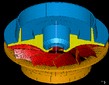
The geometric model of
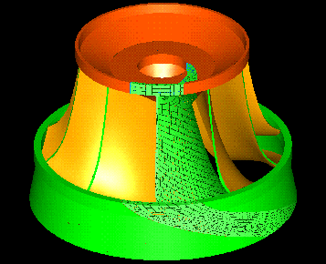
runner was assembled of three distinct parts: crown, blade and band. The geometry of crown and
band follow the drawings, whereas the surfaces of the blade were modelled by 400 points each,
transfered from the test model.
The runner consists of 10 blades and thus shows periodic (cyclic)
simmetry. The use of special boundary conditions in preparing the finite element model allows
modeling of only 1/10th of the whole runner. Thus the time needed to calculate the results can
greatly be reduced and/or accuracy of results improved. 1/10th of the geometric model has been
discretized into Solid linear brick elements (8 nodes), which, based on general experience with
FEM, are very reliable compared to 3D tetrahedrons. Care was taken to put more elements into
places, where higher gradients of results were expected. Howewer, the number of elements was
limited by hardware capabilities and reasonable amounts of time needed to solve the problem. At
the end of discretizing, the mesh consists of 7661 elements and 9892 nodes.
Boundary conditions
In the case of static loads which repeat themselves in the same way as geometry, the deformation
must reflect these periodicities and must be the same in all sectors. Therefore, the generalised
displacements on the right boundary must be equal to those on the left boundary :
{uright} = {uleft}
(the components of the displacements or rotations in the cylindrical coordinate system
which defines the simmetry must be equal on both boundaries. Secondly, the runner is attached to
turbine shaft. The structure can therefore be considered restrained in rotation and axial
displacement at the area of attachment.
Loadings
Under normal operating conditions, a Francis
turbine is subjected to two sorts of static loads, namely to the centrifugal force field due to the
rotational speed, and to the pressure of the water on the blades. The forces of the first type can
easily be calculated and applied in finite element model, whereas the pressure distribution has been
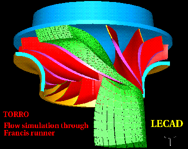
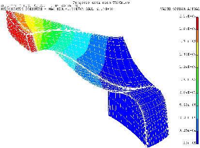
determined by the flow calculation by TASCflowTM software. The distribution is far from
being uniform and analysis shows that,
by taking uniform distribution into account, the results greatly differ from reality. Therefore,
much effort was put to obtain the accurate pressure distribution over the blade surfaces. The data
was provided by simulating the water flow through the runner and confirmed by measurements on
the test site.
i
Results
The problem was solved using I-DEAS linear static solver and calculated in
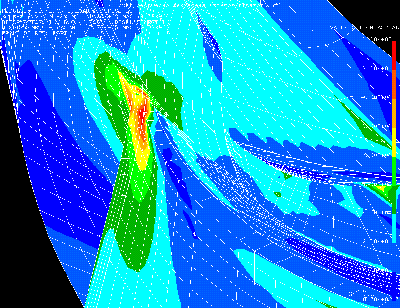
form of displacements, stresses and reaction forces. In general, torsional displacement of band is
expressed. In the case of ns=400 runner, maximum stress 93.7 N/mm2 occurs at the blade outlet edge near the transition from
blade to crown.
Modification
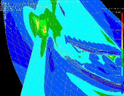
In order to lower stresses in critical area a modification of
geometry has been caried out. Modified model was analyzed once again. Results show considerable
fall in stress (~16%). Geometry modification is not expected to influence hydraulic characteristics
of the impeller since
a) the modification takes place at the crown, where no significant energy is
transfered (majority of moment is produced at greater radii)
b) beneath the impeller the air is
blown into the water stream
Conclusion
The proposed modification is easy to implement
(welding at site) and expected to lower the general stress level in critical area. Analyses has shown
that centrifugal force due to rotation does not contribute to stress significantly as does not slide
bearing effect (due to seal clearances).
